¶ Make it!
DISCLAIMER
This is not a good project for beginner electronics hobbyists. I would rate it as intermediate to advanced. See the skills list below for a better idea of what is involved.
THE ENTIRE PROJECT IS AVAILABLE IN DIGITAL FORMAT ON
SITE FOR SUPPORTING ME IN THIS WORK.
Recommended Skills List:
- Soldering – All components are either tenth inch spacing through-hole or SMD components readily available as modules with tenth inch
- headers, but you will need to solder.
- Construction and wiring of electronics
- You’ll have to make a chassis somehow, either by using my STL files and a 3D printer
- You’ll need to get printed circuit boards
- Familiarity with Arduinos and Arduino IDE.
¶ What is needed?
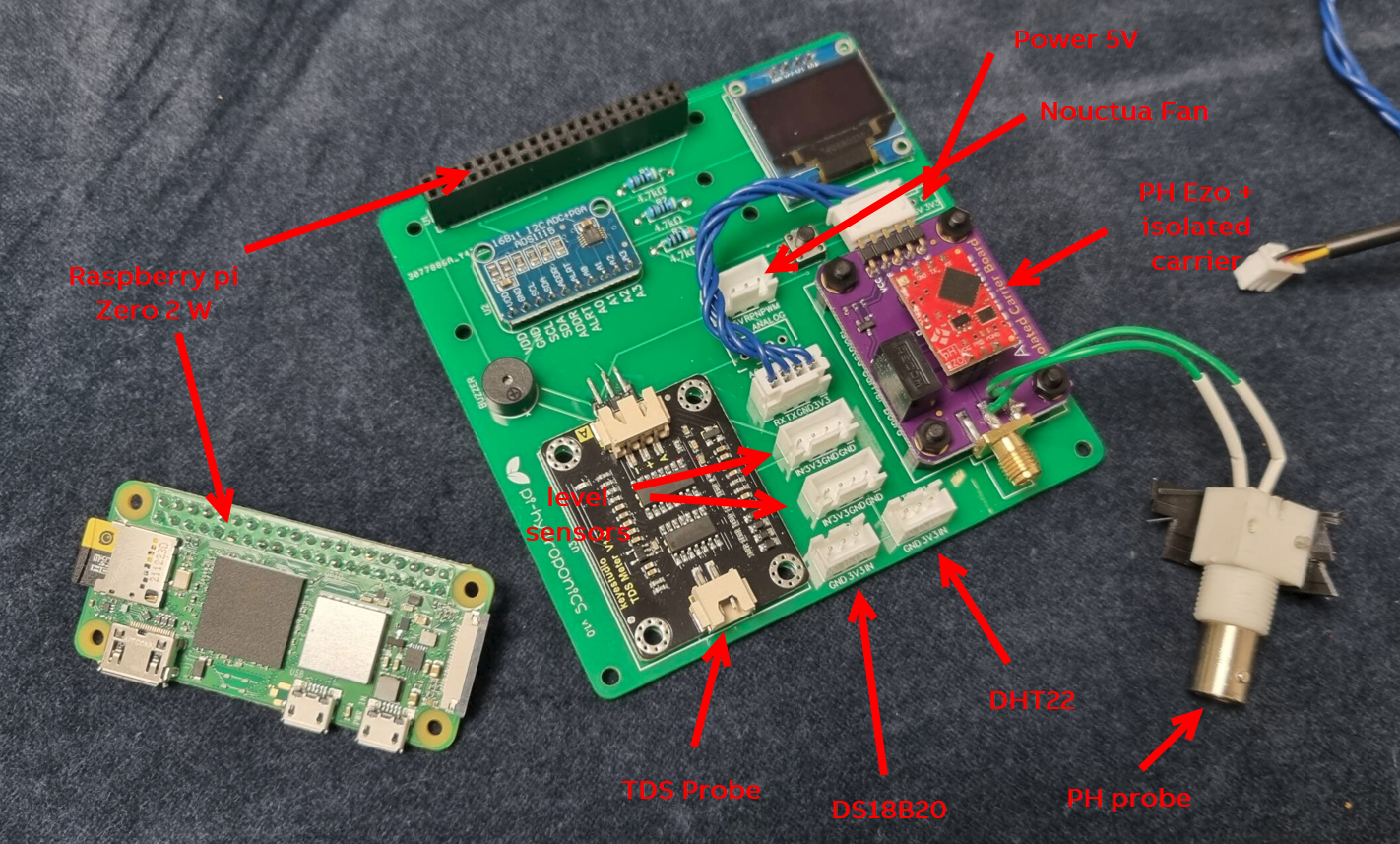
Here below the parts necessary to assembly the pi-hydroponics board:
- Raspberry Pi Zero 2W
- Any 16GB Class 10 high endurance SD card
- EZO ph circuit
- Electrically Isolated EZO™ Carrier Board
- CQRobot / DFRobot TDS meter board or compatible.
- 2x Level sensor YKC-Y25-NPN
- 3pin DS18b20 temperature sensor
- 3 pin DHT22 (optional, for room temperature/humidity)
- OLED 128x64 display I2C
- ADS1115 board 16bit adc converter
- up to 3 ESP-12F 5V/7-30V/220V 4 Channel Relay Board
- Carbon dioxide MH-Z19 sensor + esp32 (or esp8266) (optional, for room carbon dioxide level)
- JST 2.54mm pin headers
- 3 x 4.7 k ohm resistors ¼W
- USB type C panel connector
- BNC female panel connector (for pH probe)
- PLA to print the case
- M3 threads
- M3 x 12mm screws
- 1 x Noctua NF-A4x10 5V PWM ultra silent fan (optional)
¶ Build your controller
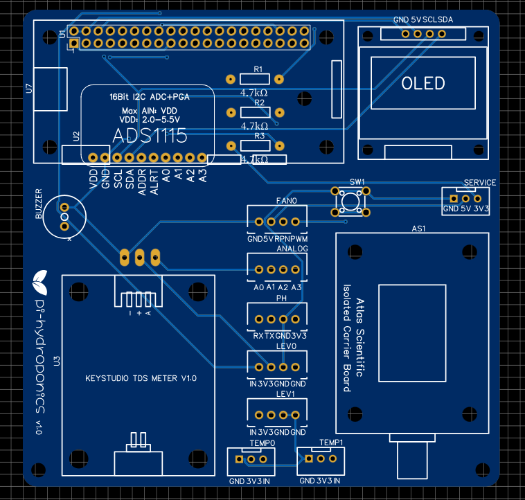
The controller has been designed to match the 40 pin Raspberry 40pin header, therefore it must be placed on top of this. The controller can work only with the following boards:
– Raspberry Pi Zero W
– Raspberry Pi Zero 2W (recommended)
– Raspberry Pi 3b+
– Raspberry Pi 4
To get the PCB with all electronics components assembled we suggest to get them all from JLCPCB or PCBway.
The cost of these PCBs is about 1.8$!!!!!! plus shipping.
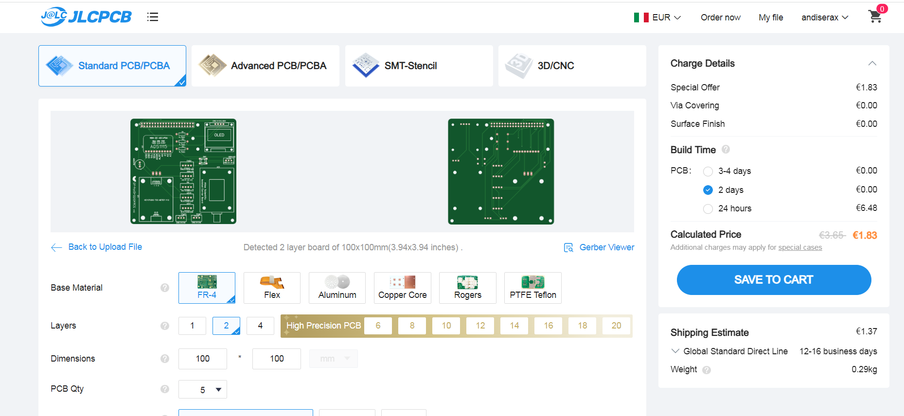
Normally you will be asked to upload the following files:
- Gerber files (.rar)
- BOM file (.csv)
These file will be provided once ordered the full project in Cults3D together with the image file containing operative system, schematics, BOM and gerber file.
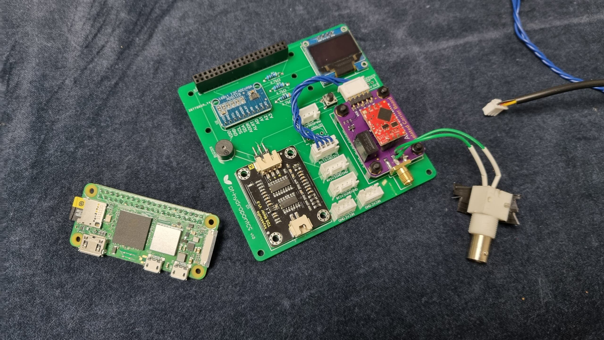
The assembly is very simple. You have just to solder some tht pins.
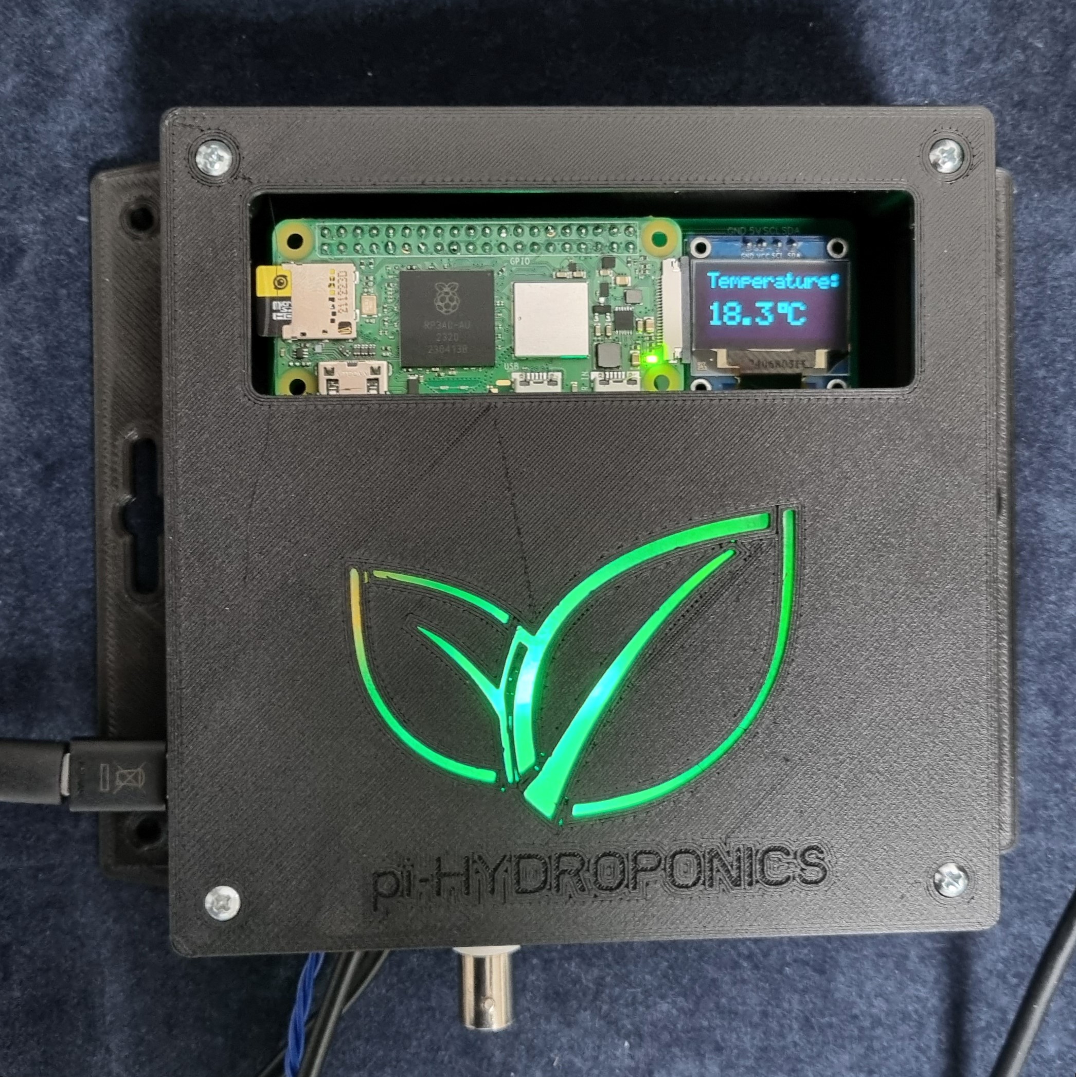
At the end of the course you should have something like the above picture.
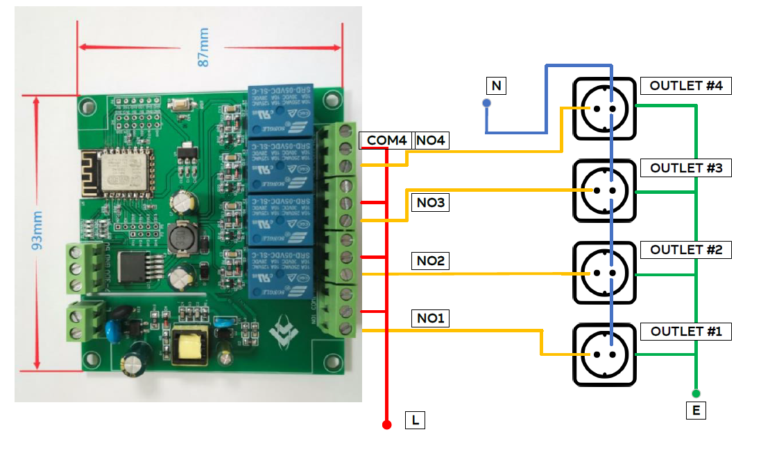
¶ Build your powerbar
The powerbar is needed to power aquarium heater and the other devices like pumps, skimmer, UV lamps.
For this device you can use ANY 4 outlets Tasmota device (UP 3 POWER BARS). You can either buy a preflashed device or you can build your own.
I recommed to use one of these devices:
- Nous 15A 3AC 3USB Power Monitoring Power Strip (about 35$)
- KRIDA 4 Channel 10A Electromagnetic Relay Board (about 16$)
- ESP32 4 Channel Relay Board (about 25$)
- ESP-12F 5V/7-30V/220V 4 Channel Relay Board (ESP12F_Relay_X4) (about 8$!!!)
Once uploaded last Tasmota firmware on device (most of them comes already flashed) you can easily configure it to work with your Oceanberry.
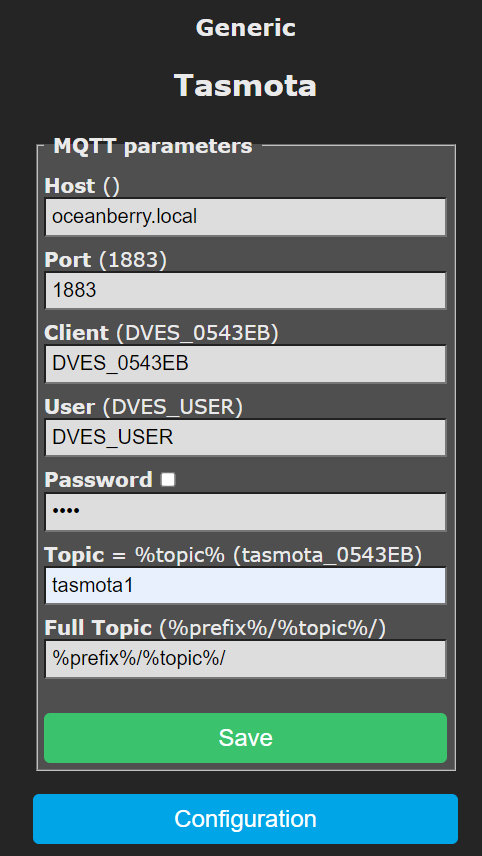
The first thing to do is connecting your tasmota powerbar to your WiFi network or to Oceanberry access point.
Then you have to write the Oceanberry IP address [Host ()] and “tasmotaX” [topic] in MQTT preferences where X is the number of the power module (from 1 to 3).
Then reboot the device.
If you need to build your powerbar make sure to connect the outlets as follows.
¶ Burn the image
The Raspberry image must be installed into SD card. We recommend to use a 16GB Class 10, high endurance SD card to ensure the maximum longevity and avoid any file system corruption.
The burn process is very simple using the provided IMG file. You can use any image burner such as Balena Etcher.
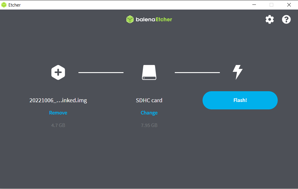

The image file can be downloaded here.
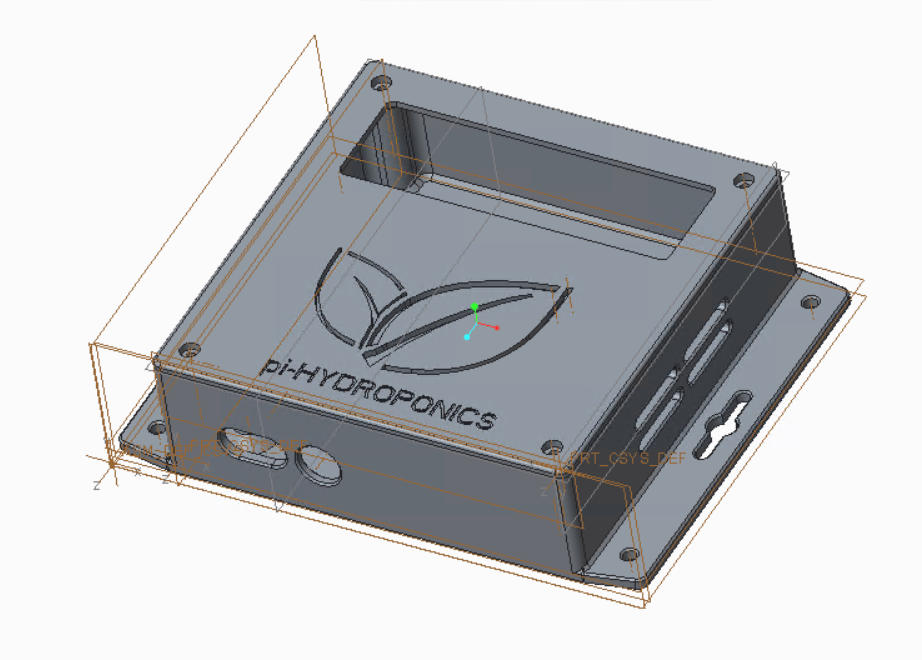
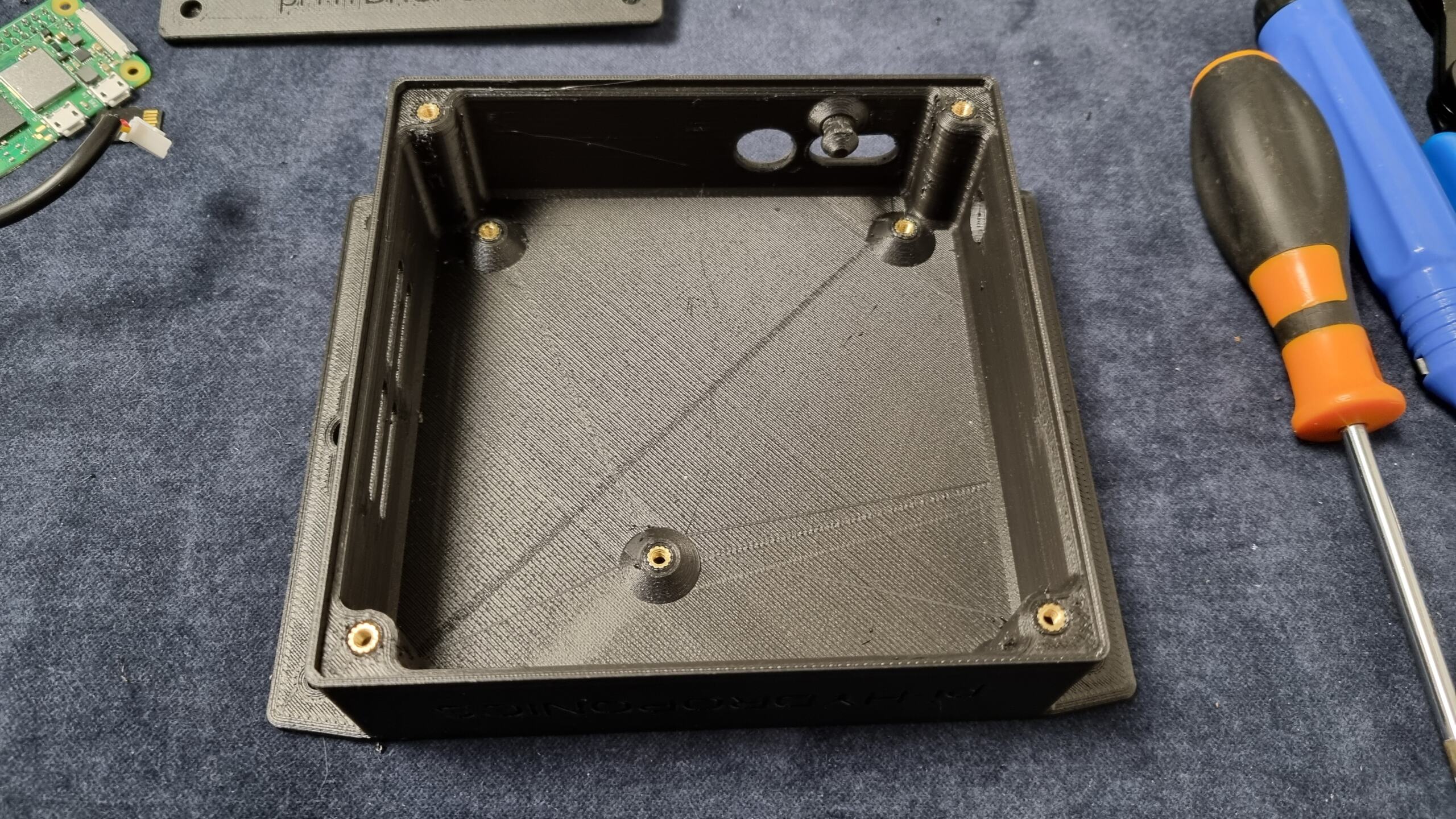
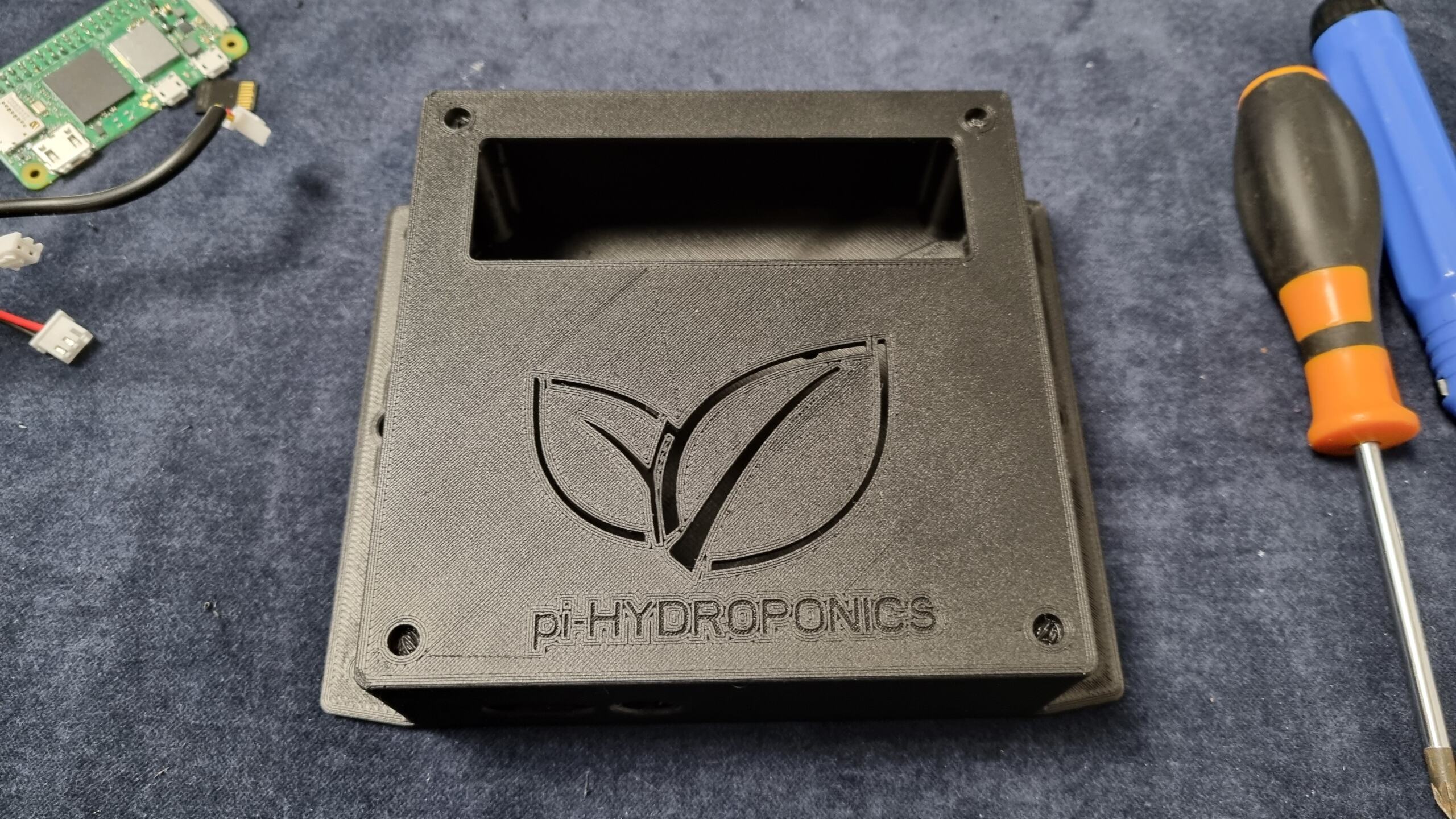
¶ Print the enclosures
Print the proposed enclosure is recommended, but not strictly necessary.
Basically you have to print enclosers for Oceanberry Controller and Oceanberry Powerbar., but any type of commercial enclosure is welcome.

If you don’t have a 3D printer, you can obviously order them all from any suitable online shop (such as JLCPCB which offer very good prices).

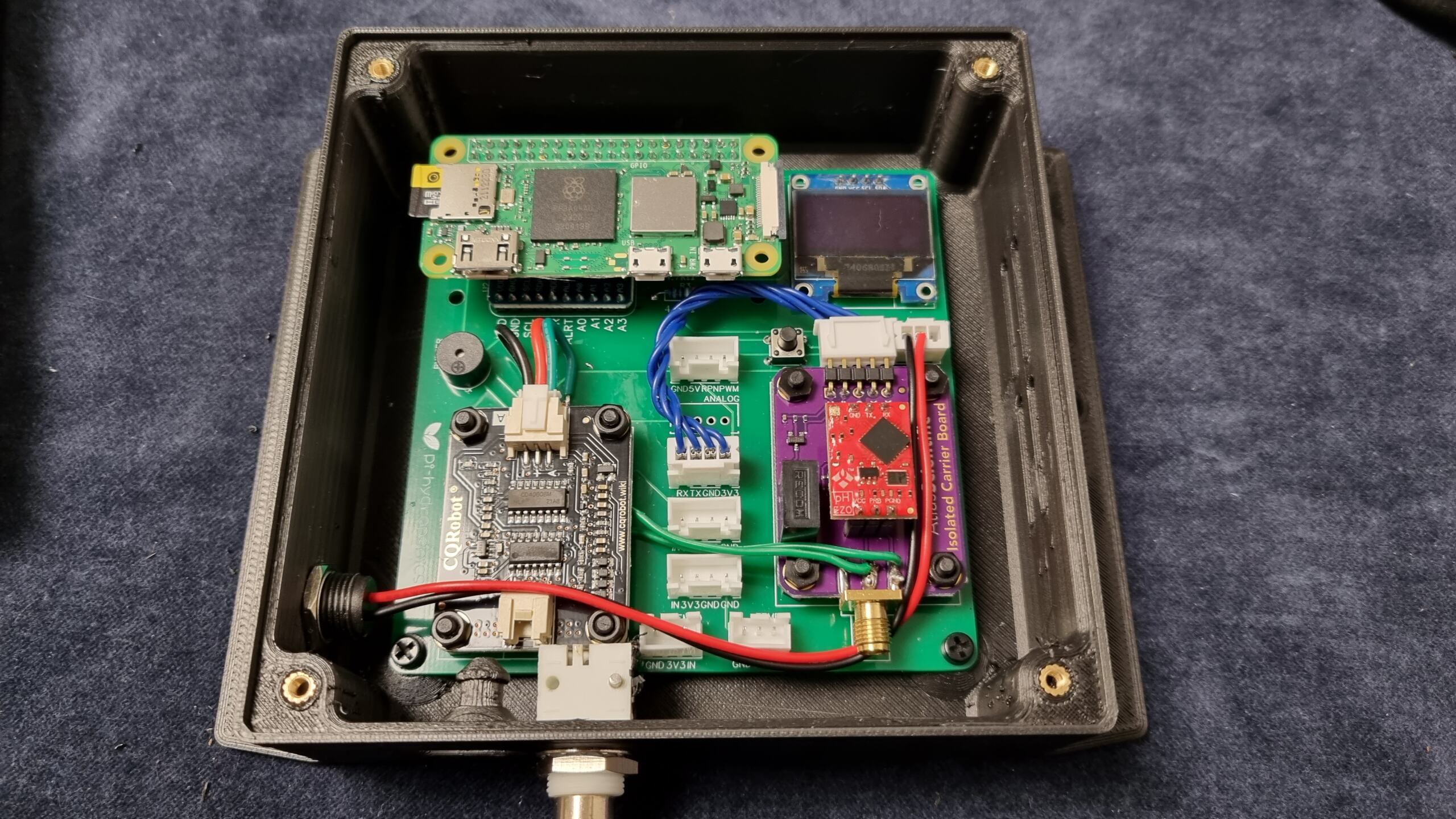
¶ Wire it up, configure Wi-Fi and connect!
Now you can connect all your sensor using the following diagrams.

Once connected to power pi-Hydroponics controller will start. The first run could take some minutes.
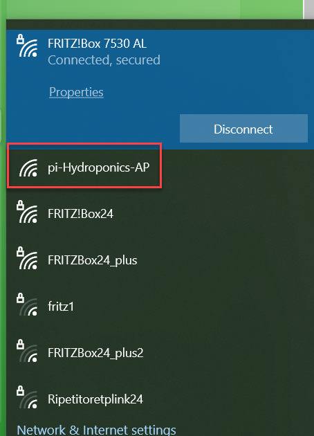
At this point you can find the “pi-Hydroponics-AP” open WiFi spot.
- Connect to “pi-Hydroponics-AP” network
- You should automatically redirect to the network manager.
- If not, connected to 10.41.0.1, or type http://pi-hydroponics.local using your favorite internet browser
- Select your network and leave the password.
- Your controller is connected to the network. You can check the IP address on your router or reading what is indicated on display.
Anyhow, it is not mandatory getting your Oceanberry connected on an existing Wifi network. You can control it just connecting on its access point “pi-Hydroponics-AP” SSID.
¶ Other hardware to get
You should by some hardware to complete you oceanberry:
- Panel USB extender
- 4 x (or 8, or 12) outlets
- fused inlet power connector IEC320 C14
- IP65 connectors for sensors